News
Your location:Home - News - Hot Topics - Detail
Part.1
Overview
In recent years, traveling wave technology has found increasing application in both transmission and distribution lines. With the development of the new power system, the structure and operational models of the power grid are undergoing profound changes. Particularly in distribution networks, the topological structure has become more complex, and there is widespread integration of distributed generation sources. These factors pose significant challenges for testing devices based on traveling wave principles. Common testing methods for traveling wave devices are no longer adequate to meet the testing requirements in the context of the new power system, primarily due to the following issues.
01
Applying impulse current method: This approach cannot authentically simulate the characteristics of actual on-site faults, fails to comprehensively assess the performance of traveling wave devices, and is only suitable for verifying the traveling wave algorithm.
02
Full-scale testing method: involves high construction costs for the test site, poses difficulties in adjusting the topology structure, and offers limited flexibility in testing procedures.
03
Real-time simulation method: The simulation step size for traveling wave testing is small, which is limited by the computational power of the real-time simulator. Consequently, the test model cannot account for complex topologies or scenarios involving new energy integration.
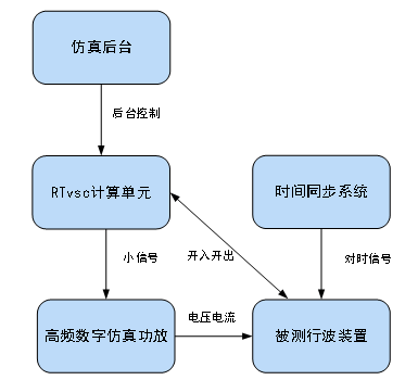
In response to the aforementioned challenges, the KETOP Simulation Center has developed the RTvsc traveling wave simulation testing system based on waveform playback. This testing system can be used for evaluating devices such as traveling wave fault locators for high-voltage transmission lines, traveling wave fault locators for distribution networks, traveling wave-based line selection devices for distribution networks, traveling wave monitoring devices, and traveling wave protection devices. Specifically targeting the typical operating conditions and output characteristics of distribution networks, collaborative development was carried out under the scientific and technological project of Zhejiang Huadian Equipment Testing & Research Institute Co., Ltd., titled "Development of a Simulation and Testing Platform for Distribution Network Traveling Wave Fault Location Devices with Insulation Warning Function Testing." The structure of the testing system is shown in the figure below
Part.2
Simulation System Parameters
2.1
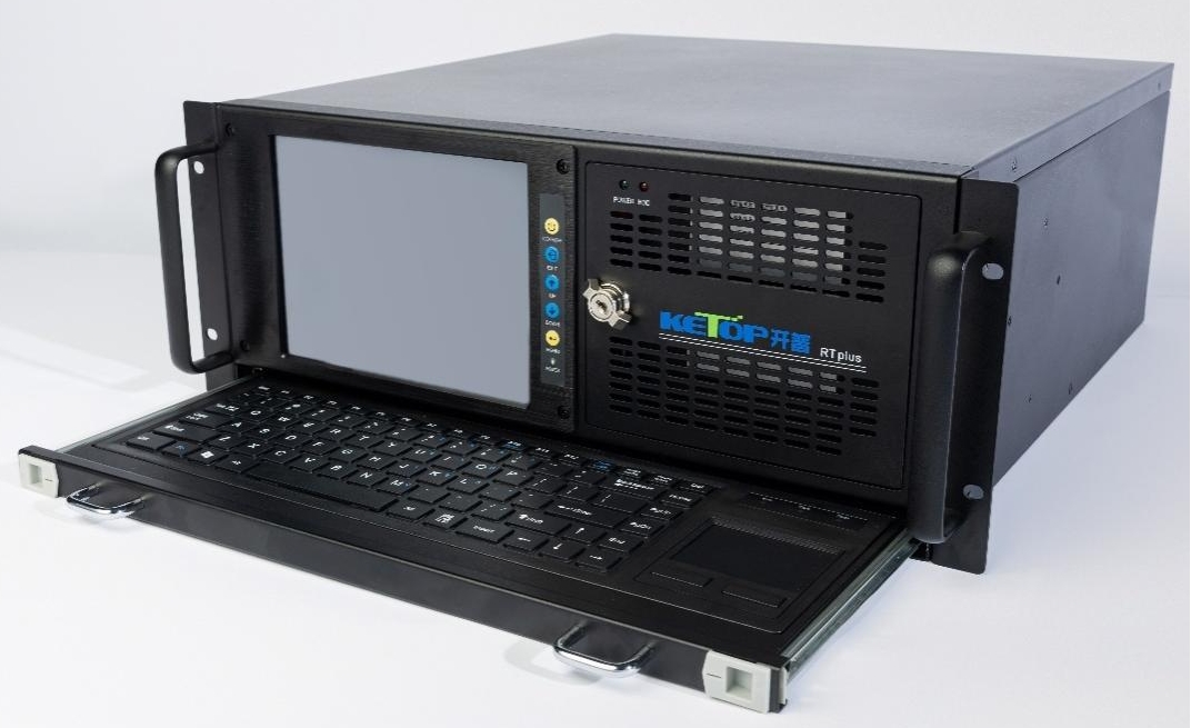
Computing Unit

◆ The computing unit is housed in a 19-inch, 4U high chassis.
◆ Equipped with a 10-core Intel i9 processor and an RT-Linux real-time operating system.
◆ Supports 16 channels of analog output, 16 channels of digital (switch) output, 24 channels of analog input, and 24 channels of digital (switch) input, with an input/output sampling rate of 1 MHz.
◆ The playback simulation step size is 1 μs, and the maximum playback waveform duration is 1 second.;
◆ Supports batch playback of multiple fault recordings, allowing configuration of the pre-fault cycle time and playback interval time.
◆ Real-time closed-loop control during playback enables synchronous output of discrete signals and recording of the device's trip contacts.
2.2
High-Frequency Digital Simulation Power Amplifier
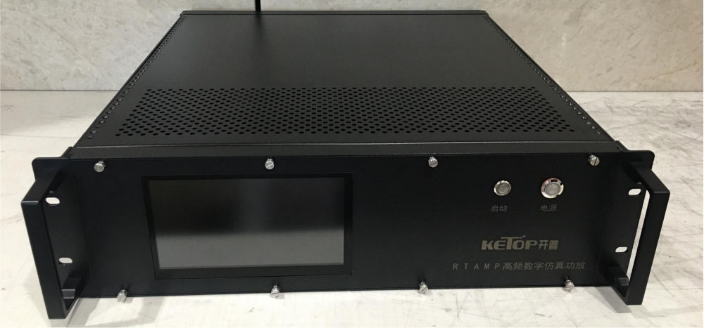
High-Frequency Digital Simulation Power Amplifier - Front View
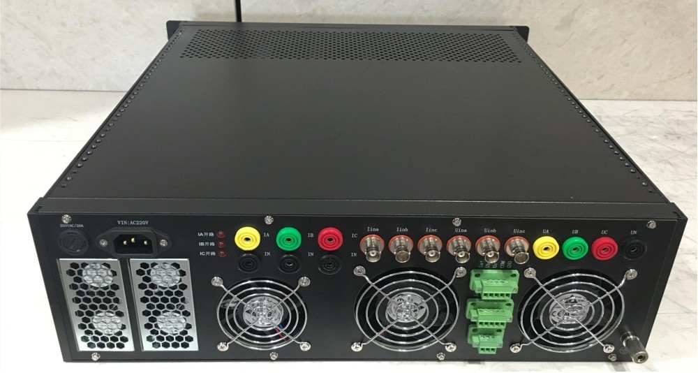
High-Frequency Digital Simulation Power Amplifier - Rear View
Frequency Range | 200 kHz bandwidth, DC-coupled |
Current Range | 40A RMS (high current, short-time duty operation) |
Voltage Range | 120V(RMS) |
Precision Metrics | Current non-linearity error is less than 0.2% Voltage non-linearity error is less than 0.2% (2V~120V) Phase error is less than 0.2 degrees |
Small-signal Accuracy | Current: 50 mA, with a deviation of less than 5 mA Voltage: 1.0 V, with an error of less than 1% |
阶跃响应时间 | 方波测试信号,电压电流均小于20us |
输入阻抗 | 大于10kΩ,差分或单端输入 |
总谐波畸变率 | 电流总谐波畸变率小于0.2% (0.4 A~40A) 电压总谐波畸变率小于0.2% (4V~120V) |
带负载能力 | 电流:直流电阻不超过0.3Ω 电压:感性负载直流电阻200Ω |
机箱尺寸 | 电压电流各3相,高度3U |
其他功能 | 液晶屏显示,电源有不平衡保护 电流有过热保护,电压有短路保护 |
Part.3
测试流程
3.1
波形生成
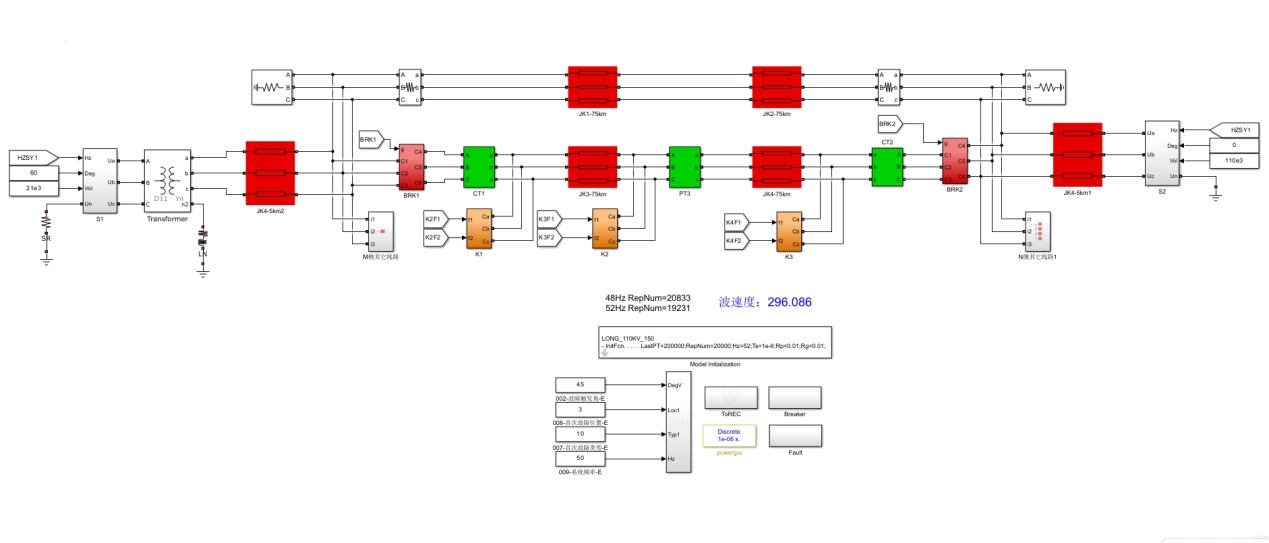
仿真模型
在Simulink上搭建相关的电网一次模型,通过在模型中设置故障参数和波形生成参数即可一键生成故障回放波形。
波形生成参数包括:LastPT录波点数、RepNum循环点数、Hz系统频率、Rp、Rg故障过渡电阻参数等。
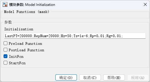
波形生成参数设置

生成的波形库
3.2
批量回放
1) 选择波形库文件夹
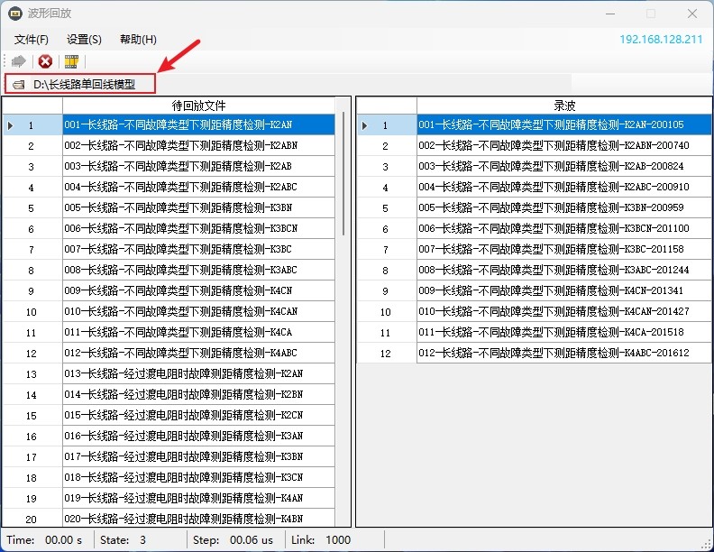
选择波形库
2) 选择回放类型
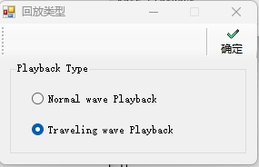
回放类型选择行波回放
3) 设置数据循环时间和回放间隔
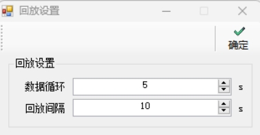
循环时间设置和回放间隔设置
4) 上传IO配置
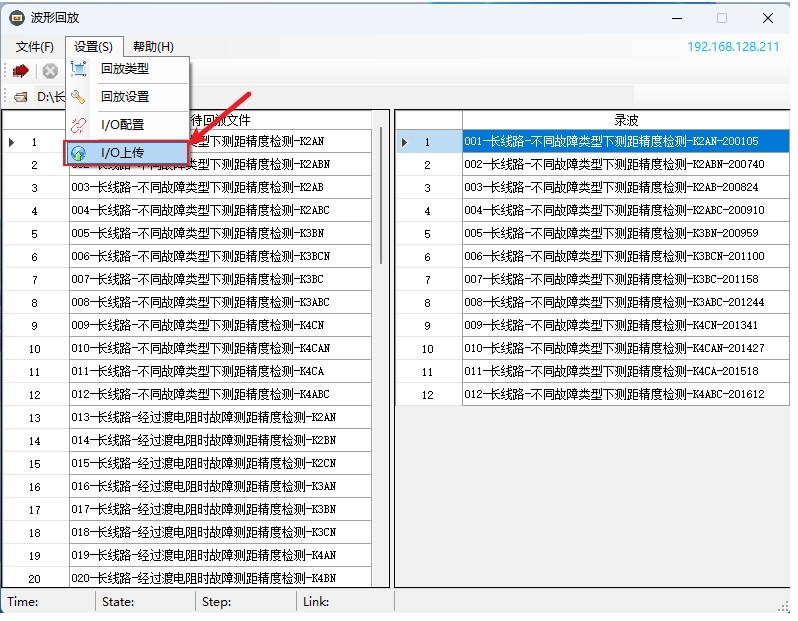
上传IO配置
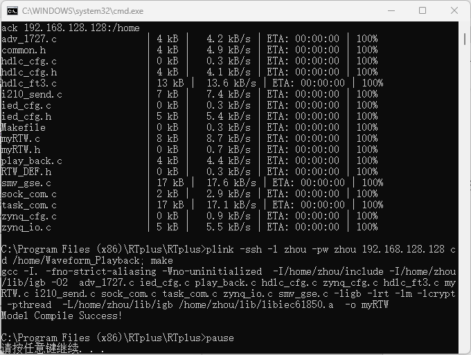
上传成功提示
5) 运行程序
点击运行程序
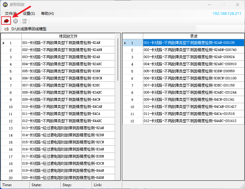
6) 执行回放

批量执行回放操作
点击上图所示的回放按钮可开始执行回放,可一键选中多个波形进行回放,回放完成的波形会在右侧进行显示。
3.3
典型测试项目
序号 | 测试项目 | 考核指标 |
1 | 不同故障类型下测距精度检测 | 基本测距精度验证 |
2 | 经过渡电阻时故障测距精度检测 | 验证高阻故障的灵敏性 |
3 | 不同故障初相角时测距精度检测 | 验证不同初相角的灵敏性 |
4 | 频偏工况下测距精度检测 | 验证行波测距不受系统频率影响 |
5 | 母线不同间隔数下故障测距精度检测 | 验证大量折反射的情况下,装置的处理能力 |
系统中性点不同接地方式下测距精度检测(配电网) | 验证系统中性点不同接地方式下装置的测距精度 |
Part.4
产品配置
RTvsc行波仿真测试系统默认配置:
序号 | 名称 | 数量 |
1 | 移动测试车 | 1台 |
2 | 仿真计算单元(16路模拟量输出、16路开关量输出、24路模拟量输入、24路开关量输入) | 1台 |
3 | 高频数字仿真功放(3路电压、3路电流) | 1台 |
4 | 后台计算机 | 1台 |
5 | 后台运行管理软件 | 1套 |
6 | 电力系统波形组态分析软件 | 1套 |
7 | 行波测试典型模型及波形库 | 1套 |
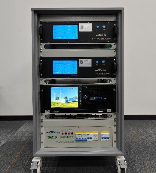
测试系统正面图
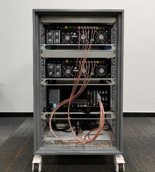
测试系统背面图
开普仿真中心致力于电力系统仿真测试及仿真相关设备研发,研发的产品包括:RTplus智能电网实时数字仿真系统、RTDT继电保护数字孪生系统、特高压直流输电控制保护仿真系统、KPF1C-RTDS Aurora数字接口装置、RTDS自动测试系统、RTbasic继电保护静模标准化测试系统、能源互联网仿真系统、KPF1D FT3/HDLC稳控接口装置、RTvsc行波仿真测试系统等。
页面版权所有:许昌开普检测研究院股份有限公司 豫ICP备15015526号-1 豫公网安备 41100202000037号